 |
 |
Manned Ornithopters Full History History Archive
Getting Started How to Design & Build Competition Info Design Tools
Design Manual Newsletter Free Plans
Teachers Guide Web Site Links
About the Society Contact Info |
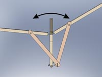
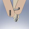
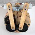
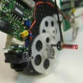
Ornithopter Flapping Mechanisms The purpose of the flapping mechanism is to convert the rotary motion of your motor into the reciprocating motion of flapping wings. There are many ways to do this, and I will describe only some of the more common ones here. The mechanism must be lightweight and fairly simple. Yet it must also provide a fairly symmetrical wing motion so the ornithopter flies straight. The basis for most mechanisms is called a "four-bar linkage". There is a rotating crank shaft, driven by the motor. As the crank goes around, the connecting rods push the wings up and down. Unfortunately, when a second wing is added, this mechanism will produce asymmetric flapping. The two connecting rods leave the crank at different angles. This causes them to act at different times. The asymmetric flapping lowers the efficiency and makes the ornithopter want to turn to one side. There are several ways to improve the symmetry:
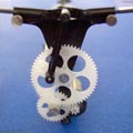
These are some of the most commonly used mechanisms for two-winged (monoplane), ornithopters. A wide variety of different mechanisms have been developed for special purposes, such as flapping multiple wings, moving the tail along with the flapping motion, or actively twisting the wing structure as it goes through the flapping cycle. Check out the free FlapDesign Software on this web site. It's an indispensible tool that allows you to figure out the correct dimensions for your flapping mechanism before you start to build.
|
|||||||||||||||||||