 |
 |
Manned Ornithopters Full History History Archive
Getting Started How to Design & Build Competition Info Design Tools
Design Manual Newsletter Free Plans
Teachers Guide Web Site Links
About the Society Contact Info |
Rubber Band Powered Ornithopters Some of the first successful ornithopters were powered by rubber band. Their goal was to figure out another way for people to fly after balloons. Experiments with rubber-powered ornithopters did help pave the way for Schmid's manned ornithopters of the 1940s. However, the rubber-band-powered ornithopter is a fascinating endeavor in its own right, today providing an excellent educational opportunity for students, as well as great enjoyment for hobbyists. Here are some rubber-powered ornithopters developed in France during the 1870s. Starting from the left, Jobert flew this ornithopter powered by a stretched rubber band turning a crank. In the following year, he built a biplane ornithopter with the twisted rubber band motor more common today. The use of four wings was a clever innovation that reduced the amount of torque needed to flap the wings. The other ornithopters shown here were built by Alphonse Penaud and Hureau de Villeneuve, respectively, in 1872.
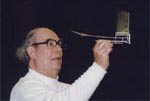
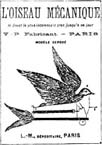
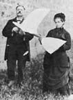
In 1874, Victor Tatin devised a more complicated crank mechanism that actively drove the twisting of the wings. His ornithopter shown here is on exhibit at the National Air & Space Museum in Washington. Most of the mechanism was fashioned from bent wire, and it is quite interesting to examine up close. A similar mechanism was used by Pichancourt in his toy bird, "l'oiseau mécanique". This was perhaps the first commercial venture involving ornithopters. Pichancourt is shown at right with his lovely assistant and the biggest rubber-powered ornithopter I have ever seen! He must have needed a huge bundle of rubber to flap those huge wings.
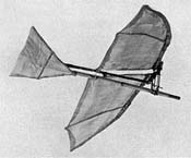
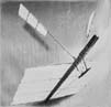
In fact, the thickness of the rubber band has to increase faster than the scale of the ornithopter. If you double the wingspan and every other dimension, the rubber band needs to be more than twice the thickness of the original. This could be corrected by using some sort of gear reduction to amplify the torque of the rubber band. However, that is not so easy to do. Lawrence Hargrave, working in the 1890s, discovered an easier solution, which many people after him have adopted. To reduce the torque requirement, he made the flapping wings smaller and provided a large fixed wing. Two examples are shown below. At left is one of Hargrave's ornithopters. The center photo shows an ornithopter built by Alexander Lippisch.
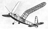
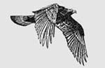
Alexander Lippisch led a group of aviation students during the 1930s. He and his students built many large ornithopters powered by rubber band and by internal combustion engines. The science of aeronautics had advanced greatly since Hargrave. These ornithopers had better airfoils and more efficient flappers, even though the flapping wings remained comparatively small. Erich von Holst experimented with various bird and dragonfly ornithopter configurations in the 1930s. His work included experimentation with biplane wing phasing and hinged outer wing panels. Some of his rubber-powered ornithopters achieved a very high level of realism, as in the example shown above. He used pulleys to increase the torque.
By coupling the upstroke of one wing to the downstroke of another, two other benefits were achieved. First, the upstroke could procede more slowly, so the wing could continue producing lift during the upstroke. Second, the lift on that wing would partially offset the force required for the other wing's downstroke, reducing the overall torque requirement.
With these innovations, ornithopter flight times increased from around four minutes, to the current record of 21 minutes, 44 seconds held by Roy White. Successful competition models are extremely light-weight and delicate. Careful adjustments must be made to maximize the flight time without hitting the ceiling. Perhaps as you refine your ornithopter skills, you will be able to log some impressive flight times of your own.
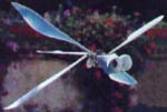
The rubber-band-powered ornithopter also offers a range of interesting projects, aside from duration contests. Shown above: Ken Johnson's lifelike butterfly model. John White's ornithopter in which the tail moves as well as the wings. Albert Kempf's dragonfly using a geared rubber band motor and foam wings.
|
||||||||
 Indoor
ornithopter contests began in the 1930s. A model airplane club called
the Chicago Aeronuts was holding various contests for the indoor
flying of model airplanes. For some extra challenge, they decided
to add ornithopters to the list of events. Ed Lidgard's design shown
here could be built from magazine plans, and many of the rubber-band-powered
ornithopters built over the subsequent decades followed a similar
pattern. Eventually the ornithopter event became part of the national
contest arranged by the Academy of Model Aeronautics.
Indoor
ornithopter contests began in the 1930s. A model airplane club called
the Chicago Aeronuts was holding various contests for the indoor
flying of model airplanes. For some extra challenge, they decided
to add ornithopters to the list of events. Ed Lidgard's design shown
here could be built from magazine plans, and many of the rubber-band-powered
ornithopters built over the subsequent decades followed a similar
pattern. Eventually the ornithopter event became part of the national
contest arranged by the Academy of Model Aeronautics.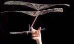 In
the 1980s, it was found that biplane ornithopters had a huge advantage
in these indoor flying contests. With monoplane ornithopters, much
energy was lost at the end of each wingstroke, when the crank went
through its "dead center" position and snapped forward
without doing any useful work. With four wings, you can set it up
so one pair of wings is in mid-stroke, maintaining a load on the
crank, while the other pair is at the end of its stroke. The cranks
don't reach dead center at the same time, so the crank doesn't snap
forward, we can harness the energy of its full rotation, and the
smoother flapping motion allows overall weight reduction.
In
the 1980s, it was found that biplane ornithopters had a huge advantage
in these indoor flying contests. With monoplane ornithopters, much
energy was lost at the end of each wingstroke, when the crank went
through its "dead center" position and snapped forward
without doing any useful work. With four wings, you can set it up
so one pair of wings is in mid-stroke, maintaining a load on the
crank, while the other pair is at the end of its stroke. The cranks
don't reach dead center at the same time, so the crank doesn't snap
forward, we can harness the energy of its full rotation, and the
smoother flapping motion allows overall weight reduction. 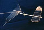 Another
modification was to move the stabilizer to the front of the model.
With the flapping wings at the back of the motor stick, the stabilizer
could be positioned directly above the motor stick and in clean
air where it could function more effectively as a lifting surface.
Another
modification was to move the stabilizer to the front of the model.
With the flapping wings at the back of the motor stick, the stabilizer
could be positioned directly above the motor stick and in clean
air where it could function more effectively as a lifting surface.